
General
– Happens During Audio Signal Processing
– in Short, All Man Made Systems have their Limits and Aliasing Happens when a Device Processes Data which goes Beyond the Devices Restrictions
– in Digital Audio it means, when a Signal has a Wider Spectral Content than a Digital Audio Workstation can Work with
– in a DAW Aliasing is Created when the Signal Goes Above the Maximum Supported Frequency
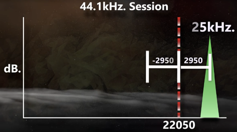
– e.g. in a 44.1 kHz Session the Maximum Supported Frequency is 22050Hz, Anything that Goes Above 22050Hz will be Reflected Down the Spectrum in Equal Measure
– i.e. the Signal that Crosses the Maximum Supported Frequency of 22050Hz by 2950Hz is Found Back in the Audible Range at 19100Hz
– so when a Signal Goes to 25000Hz it is 2950Hz Above the Maximum Supported Frequency, 22050Hz – 2950Hz = 19100Hz
– Besides, the Audio Processing itself can Produce Extra Harmonics, as a Result of the Signals Changes it Performs
– Compressors, Limiters, Saturation, Ring Modulators etc. are just a Few that Alter the Signals Amplitude and may cause Extra Spectral Data
– Anything that Generated Harmonics Such as Compression / Saturation will Likely Go Over the Maximum Supported Frequency
– e.g. an Example is when You Saturate a Sine Wave at 7500Hz with a 3rd Order Distortion Plugin you Generate Harmonics 3 Times the 7500Hz which is 22500Hz and the 450Hz that are Above will End Up at 21600Hz, this is Not a Big Issue but Imagine 5th Order or 7th Order Harmonics, e.g. 7500Hz x 5th = 37500Hz, so 22050Hz to 37500Hz is 15450Hz Above the Maximum Supported Frequency and will be Reflected Down at 6600Hz (i.e. 22050Hz – 15450Hz = 6600Hz)
– the Problem with this that the Harmonics that Aliases and are Reflected Down will Likely Not be Whole Numbers of the Fundamental and Sound Unmusical / Disharmonious plus can Cause Phase Cancellation (as the Folded Back Harmonics May be Rotated in Phase and then Meet Other Phase Position and Cancel)
– you can Mimic Audio Aliasing with a Sine Wave and then Use a Bitcrusher to Reduce the Sample Rate
– to Avoid Aliasing, Extra Frequency Content Must be Removed Before getting into the Computer, which is One of the Audio Interface Functions
Avoid Aliasing
– to get Rid of Unnecessary Components caused by Aliasing, Up-Sampling or Oversampling is a Good Solution and should be used Especially for Processes that Produce a High Level of Distortion (Not necessary with Gentle Compression or Gentle Equalization)
– Another Way Around this is to Work at Really High Sample Rates (e.g. 96000Hz) which then Provides a Frequency Range of 48000Hz, i.e. if a Signal Goes Above the Maximum Supported Frequency of 48000Hz it will Unlikely Fold Back into the Audible Range Below 22000H
– Another Way Around is to Use Oversampling which Places a Low Pass Filter Right Below the Highest Frequency to Ensure No Harmonics can Exceed the Supported Frequency, Notice that Such a Steep Low Pass Filter Must be Linear Phase to Not Introduce Phase Rotation and Linear Phase is Known for Causing Pre Ringing Distortion, i.e. the Greater the Oversampling the Greater the Latency from the Filter and thus Higher Pre Ringing Distortion
– Another Way Around is to Use Distortion in Certain Frequencies (i.e. Crossover Split)
– Another Tip is to Use an RMS Compressor Before Clipping to Reduce the Chance of Aliasing
– Another Tip is to Use an Quality High Cut Filter Such as TDR Ultrasonic Before Compressors / Limiters / Saturation to Reduce the Chance of Aliasing in the Form of Intermodulation
Visual Test Amplitude Modulation
– Test DAW “Aliasing Behavior” by Dealing with Amplitude Modulation Caused by a Limiter
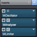
1) Insert an Oscillator, followed by an Limiter and an Analyzer
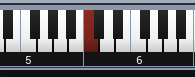
2) Set the Oscillator to a Sine at C6 (2096Hz)
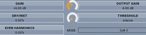
3) Use MLimiter in “Clip 3 Mode” as it Creates a Number of New Harmonics
– also Boost the Limiter by 6dB but Compensate the Output Gain to -6dB (as we Not need a Level Boost but only the Limiters Algorithm)
– lastly Set “Even Harmonics” on the Limiter Side to “0”
4) Right Now, we should See One Pulse at 2096Hz in the Analyzer
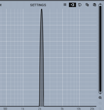
5) If we Increase the Dry/Wet on the Limiter Side, we Now have Additional Harmonics
– the Ones (1st Row) Fall Down from Fundamental to the Right are Harmonics Added by the Limiter
– but the Ones (2nd Row) Fall Down from the Right to the Left is Aliasing
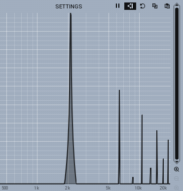
6) This Aliasing is a Result of MLimiter Transforming the Incoming Sine Wave into a New Signal whose Total Frequency Response Stretches Much further than the DAW can Accept (in this Case Cubase +RME)
7) However, that Extra Content Can Not simply Disappear, i.e. the DAW Folds the Extra Content Back into a Frequency Range that the DAW can Work in
8) If we Pitch the Oscillator Up, the New Frequency and the Consecutive Harmonics will Move to the Right
– at the same Time the 2nd Row is Moving in the Opposite Direction
– if you Do a Fast Up/Down Pitching it Sounds as if you are Tuning FM Radio
– and those New “FM Radio Aliasing Harmonics” have Nothing in Common with the Original Audio
9) As this is a Sine Wave only, Imagine how many “Aliasing Harmonics” a Complex Signal would Generate
– even if it wont Manifest itself as Loud as Music, you will Get an Impression of an Unpleasant Sound
10) To take Care about these Absolutely Unnecessary Components, Up-Sampling or Oversampling is a Good Solution
– i.e. Increase the Sampling Frequency of a Particular Plugin is Working with
– or the Sampling Frequency the Whole DAW is Working with
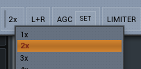
– here we Increase the Sampling Frequency of MLimiter to 2x and Aliasing is Nearby Gone
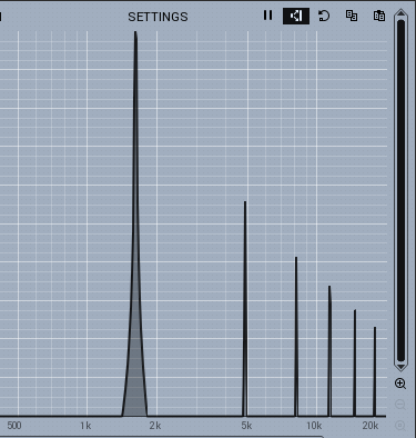
– but if we Lower the Resolution of the Analyzer, we Still Experience Aliasing visually although the Amount is Considerable Quieter
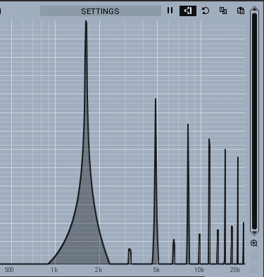
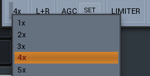
– Increase to “4x” to get Rid of Aliasing (Higher than 5x takes too much of CPU Power)
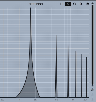
12) Up-Sampling a Audio Signal Involves Filtering in the Algorithm which may Introduce Delay or so Called Latency, i.e. the Time Needed for a Filter to Process Data
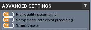
– Melda has a “High Quality Up-Sampling” for Best Results at the Cost of Latency (Turn it Off for Live Shows)
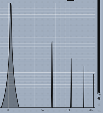
13) Finally some Test Results of Cleaning the Aliased Signal with better DAW Sampling Rates
– the Analyzer Resolution is at -170dB
Aliasing at Different Sample Rates
44kHz
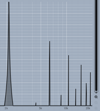
48kHz
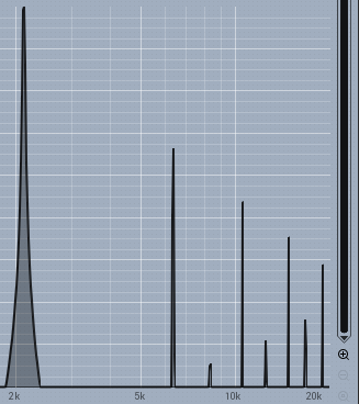
64kHz
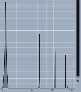
88kHz
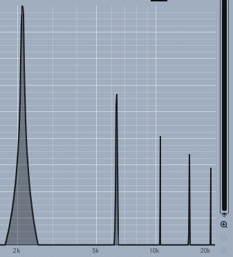
96kHz
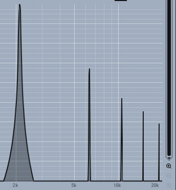
176kHz
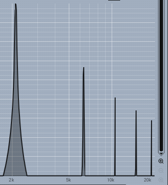
192kHz
Leave a Reply