General
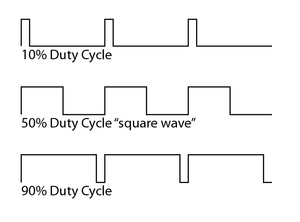
– while a Square Waveform has Equal Time between Maximum Voltage and Minimum Voltage, a Pulse Width is Essentially a Square Wave with an Adjustable Amount of Time in between Each Cycle before the Voltage Drops from Maximum to Minimum
– the Percentage of Time that the Signal is High is Known as a “Duty Cycle”
– Often was Put on Single Oscillator Mono Synths to Give them the Sound of Oscillators Beating Each other cause there is a Slight Tuning Variation Happens
– Basically the Voltage from the LFO Oscillator is Applied to the Pulse Width and allows the LFO to Vary the Pulse Width
– so the LFO is Turning the Knob for you Behind the Scenes, i.e. you Directly Turn the PW Knob and just Change the LFO Rate to Increase or Decrease the Pulse Width Range / Shape
– Roland later Introduced 2 Oscillators with Pulse Width Modulation (cause it Sounded Interesting on its Own)
Real World Example
1) a 10 Volt DC Switched On / Off Generates a Square Waveform with 10 Volts at 50% of the Time and Zero Volts at 50% of the Time (Corresponds to 1.355kHZ)
– Results in an Average Voltage of 5 Volts because 50% of 10 Volts is 5 (50:10)
– i.e. a “Duty Cycle” of 50%
2) if you Know Switch On / Off a DC Voltage to 11 Volt you get just 10 % of the Time PW and the other 90% is Zero (Corresponds to 1.428kHZ)
– Results in an Average Voltage of 1 Volts because 10% of 10 Volts is 1 (10:10)
– i.e. a “Duty Cycle” of 10%
3) This is basically Pulse width Modulation, i.e. Change the Average Voltage Scene by a Circuit
Leave a Reply